What does a Scene have in it?
Scenes have palettes and editors. You use them to add, delete, and change items in your scene.Palettes and Editors
Scenes have several parts. First, they have a palette. The palette is where you can find built-in art assets to use for a game. You can get your own, but this gives you a place to start. Second, they have an editor. The editor lets you add, delete, and change things for your game.
Getting Around
To use the scene editor, notice there are two tabs that seem related. First, there is a scene tab, which is a list of all the items in the scene. Second, there is a palette tab. This tab contains all of the default items you can place into a 2D or 3D scene. We can navigate between tabs using CONTROL + TAB or SHIFT + CONTROL + TAB on Windows and CONTROL + [ or CONTROL + ] on Mac. We can also click on the tabs with the mouse.
The scene tab contains the camera and the items in the game. In it, we can control the camera properties, delete items, or find them in the scene. In contrast, the Palette Tab contains images or models that can be placed inside of a scene. There are default (open licensed) art objects that can be used freely in any project as a starting point. This provides a way to add, for 2D games, basic tiles for dirt, water, stone, monsters, and other items for use in a potential game. In each case, the art is appropriately labeled so that users can see the image and get accessible information about it. All default art is child-appropriate and should be usable in or out of a classroom.
The 2D Grid Editor
Modern computer gaming uses both 2D and 3D graphics. To say the least, 2D is simpler for many reasons, especially the math behind the scenes. The metaphor used in many scene editors is one of a grid. In 2D, we have x and y coordinates and in 3D we add z. This means that for 2D, we can add items to any horizontal and vertical value. For 3D, it is the same idea, except a z coordinate can push the item forward (positive z) or backward (negative z), by default. Computer games use numbers not integers, so 1.5 or 1 are both fine.
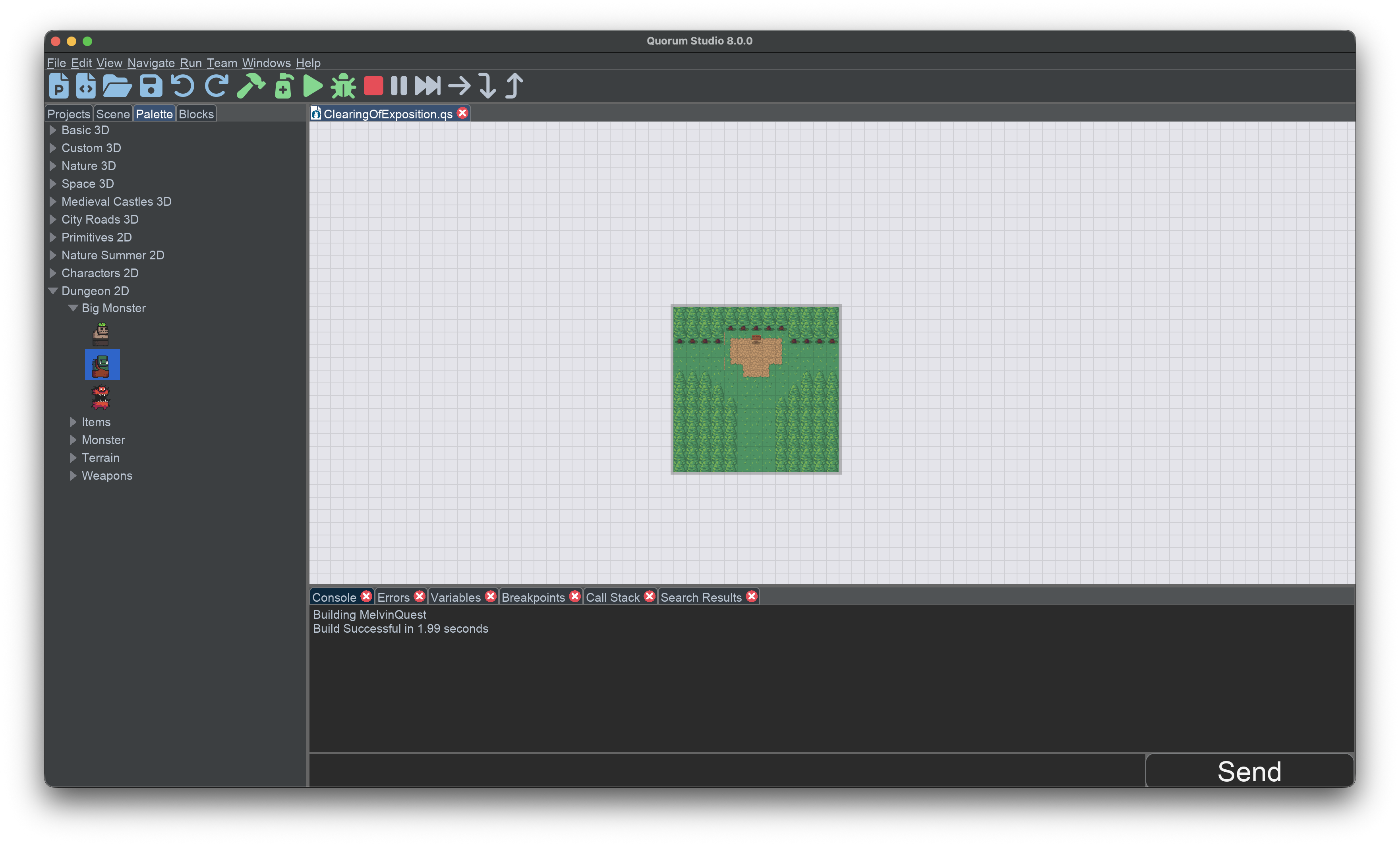
Consider an example. In the image below, there are horizontal and vertical lines. They are drawn on the screen for the editor, but do not show up in your game. By default, these lines are spaced 32 'units' apart from each other, which for this 2D editor is pixels. This default is set because many open-source art tilesets have a fixed size. Basically, the system then stores many images with many items in them. They may use 32 or 16-pixel squares for map layout.
Past this, the image below has a green section, which is a layout a person added for their game. In this case, the tiles are just images in a row, but this highlights why scene editors are helpful. A human writing down each coordinate of each item in code is time consuming. Having a tool let you place them around is easier. In the editor, each, so-called, tile can be adjusted in many ways.
The math to find the position of each square on the grid can be a little tricky. Suppose there is a grid cell size of P, where P is 32 pixels. This means that to determine the grid coordinate, we always take the grid cell and multiply by P. For example, a cell at position (10, 10) would be (P*10, P*10), or (320, 320). This is important when setting properties to objects in a 2D scene.
The 3D Grid Editor
Placing items in 3D is similar to 2D. Just like in 2D, you can select items and put them in the scene at an x, y, and now z position. Just like before, x means left and right, y means up and down, and z now means forward (positive) or backward (negative) in relation to the camera. The camera may be pointed in a direction of your choice, but by default it is on the y-axis looking down.
This idea, that z moves you forward in relation to the camera if positive is critical to understand. That the camera can be pointed in any direction is thus confusing but also important. In computer science, there is a fancy name for it called the left-handed rule. Different areas of science uses different rules for z (e.g., physics right, pilots z goes down).
One common sense way to think about the z coordinate in 3D is to put your arm or leg in front of you. That is a positive z if you are the camera looking out. Putting your arm or leg behind you is a negative coordinate. In graphics, this means that if the item is in front of the camera, a larger z would make an item look smaller because it is farther away. A smaller z would make the item look larger because it is closer. Too far away or behind the camera makes the item disappear. The camera is the same but can also look at things, called its direction. For example, it might be at an x, y, z position and looking at a different one.
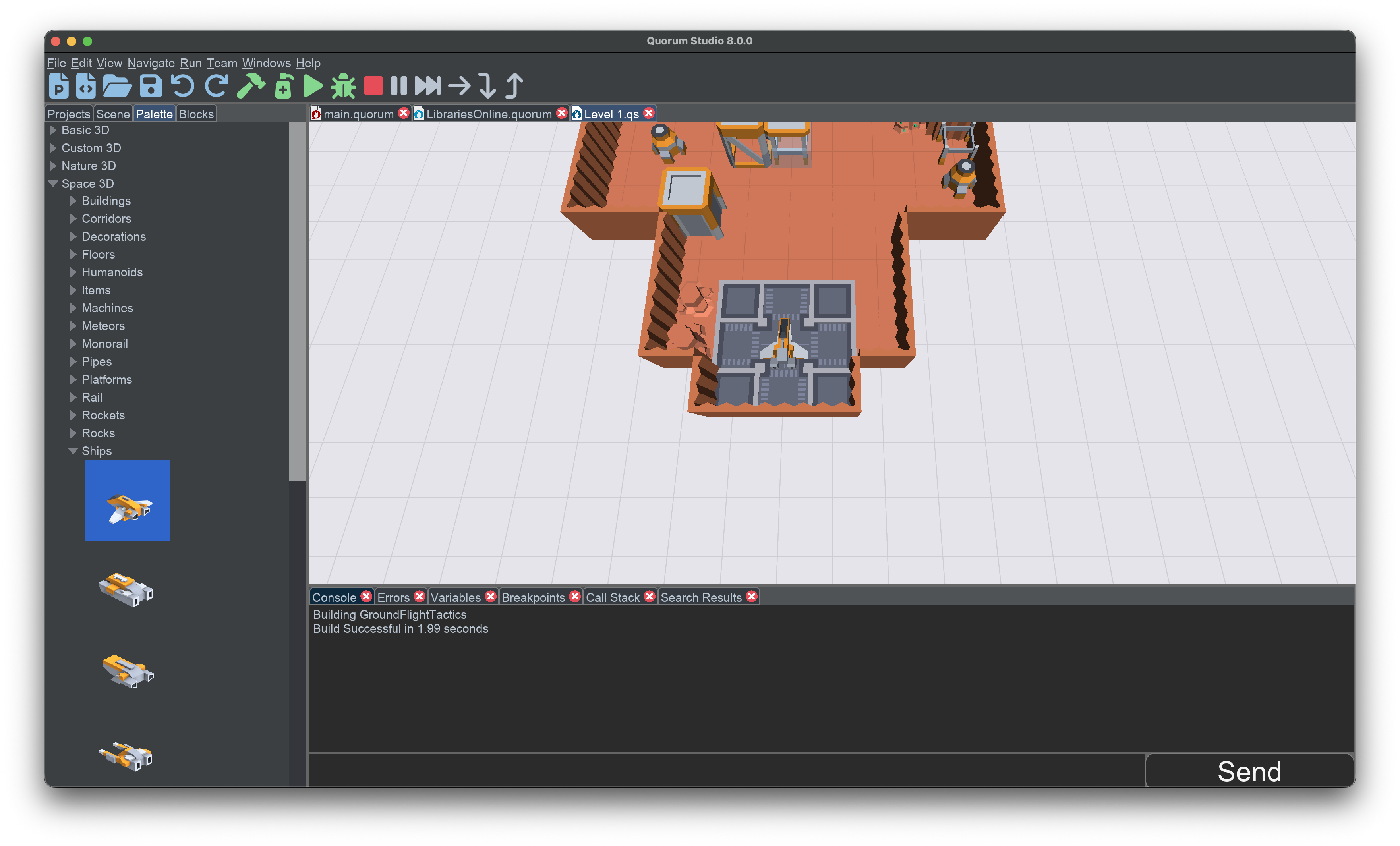
Consider the image below. In it, there are a series of walls and a spaceship. The camera is pointed at the spaceship from above at an angle. For the grid, there are a series of lines extending to infinity on the x and z axis, forming a plane. The up and down, or y axis, does not have gridlines but has the same unit measurements and movement as x and z. By default, these lines are spaced 1 'unit' apart from each other. In 2D, pixels has no physical meaning, but in 3D, one unit is a meter. The reason for this is we can then set properties on items and use real-time physics in our game. The meaning matches that of the physical world. The camera in this game is the editor camera. Your game can use any kind of camera it wants. As such, you must it in your game if you want it to be the same as it is in the editor.
The math to find the position of each square on the grid can be a little tricky. Suppose there is a grid cell size of P, where P is 32 meters. This means that to determine the grid coordinate, we always take the grid cell and multiply by P. For example, a cell at position (10, 10, 10) would be (P*10, P*10, P*10), or (320, 320, 320). This is important when setting properties to objects in the scene.
Next Tutorial
In the next tutorial, we will discuss Add and Remove Items in Scenes, which describes adding and removing items in scenes in Quorum Studio.